Guide to build Bluetooth control car and its mobile application.

I2A PROJECT 01 :BLUETOOTH CONTROL CAR
Author: Masood Akhtar Vaheed
Why this blog ??
The answer is simple whenever one try to study from from video tutorial the process of building a IOT device from it becomes easy as you follow steps directly and apply it. But, there's a small issue in that not all tutorial give you concept or guided materials for learning.
My objective to write this blog is to give as much detailed information as possible to make you learn about a particular project and make you apply your own ideas to it.Also the information and link's which,I provide in this blog will directly make you to focus on the concepts and its application.
OBJECTIVES OF THE PROJECT:
- Preparing circuit diagram.
- Coding the Arduino Uno Board.
- Code logic and explanation.
- Creating app using MIT app inventor.
- Working
COMPONENTS :
************************************************************************************
Note: The purchase links below is for your own reference. I do not earn any commission for it. It's not mandatory to purchase from here you can buy it from any other online sites or from a retailer store.
***********************************************************************************
1. Bluetooth Module ( HC-05)

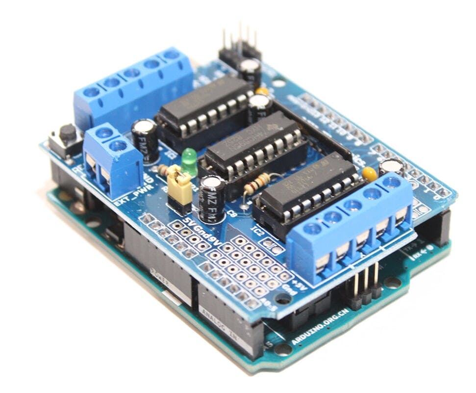
2. L293D Motor driver shield
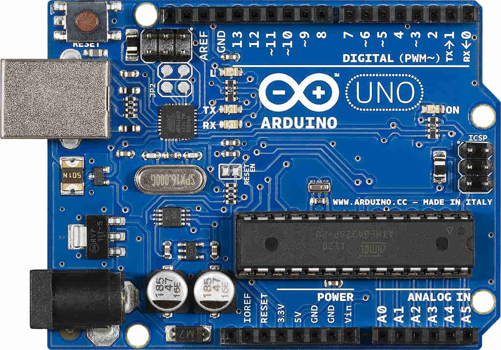
3. Arduino Uno development board
*********************************************************************************
Note: Make sure you purchase the Arduino Board having ATM328P IC visible on it as shown in the figure.
**********************************************************************************
4. Jumper Wires

5. 9V Battery with Connector

6. Robokit Chassis Setup:

In spite of purchasing each and every product it will be better to purchase this following kit as this kit is more cheaper.
Pre-requisites to know before coding:
One should be familiar with
- Working of Arduino Board
- Knowledge of all the pins in Arduino Board (i.e, digital,analog,ground,power pins etc)
- Basics of Arduino coding
i.e. Basic functions , loops (if-else,while etc.),header files. - Idea on AFMotor library
CIRCUIT DIAGRAM :
Step:01 Connect the Bluetooth module as shown in the circuit diagram.

Step:02 With the wires pinned to Arduino board place the motor shield on the Arduino board as shown in the circuit diagram.
Step:03 Connect motor 1 and 2 with motor shield using the wires as shown in the circuit diagram.

Step:04 Connect 9v battery or Li-ion battery pack with motor shield using the wires as shown in the circuit diagram.

********************************************************
Note:
The While uploading program make sure that you disconnect RX and TX pins and then upload the program or else you will be getting error while uploading the program on the board.
********************************************************
CODING:
/****************************************************************************************************************
This program is for controlling Bluetooth car.
Header file used here is AFMotor.h
This program helps the Arduino board to read the data coming from the Bluetooth module and to act accordingly
with the help of AFMotor library
******************************************************************************************************************/
#include <AFMotor.h> // It includes motor shield library
AF_DCMotor right_motor(1, MOTOR12_8KHZ);
AF_DCMotor left_motor(2, MOTOR12_8KHZ);
String readString;
void setup() {
Serial.begin(9600);
right_motor.setSpeed(250);
left_motor.setSpeed(250);
}
void loop() {
while(Serial.available()){
delay(50);
char c=Serial.read();
readString+=c;
}
if(readString.length()>0){
Serial.println(readString);
if (readString =="FORWARD"){
right_motor.run (FORWARD);
left_motor.run (FORWARD);
delay(500);
}
if (readString =="BACKWARD"){
right_motor.run (BACKWARD);
left_motor.run (BACKWARD);
delay(500);
}
if (readString =="LEFT"){
right_motor.run (FORWARD);
left_motor.run (BACKWARD);
delay(500);
}
if (readString =="RIGHT"){
right_motor.run (BACKWARD);
left_motor.run (FORWARD);
delay(500);
}
if (readString =="STOP"){
right_motor.run (RELEASE);
left_motor.run (RELEASE);
delay(500);
}
readString="";
}
}
CODE LOGIC EXPLAINED:
1. "#include <AFMotor.h> " This line tells the Arduino interface that we are using a library called as AFMotor.
2. " AF_DCMotor right_motor(1, MOTOR12_8KHZ); "
Using AF_DCMotor object we are specifying the motor number and its frequency.
3. "String readString;"
We are declaring readstring as an string object.
4.
void setup() {
Serial.begin(9600);
right_motor.setSpeed(250);
left_motor.setSpeed(250);
}
We are In void loop we are setting baud rate 9600 by using serial.begin. Also we are setting the motor RPM using setSpeed().
void setup() {
Serial.begin(9600);
right_motor.setSpeed(250);
left_motor.setSpeed(250);
}
We are In void loop we are setting baud rate 9600 by using serial.begin. Also we are setting the motor RPM using setSpeed().
5. In void loop( ) the logic is simple. using Serial.available( ) we are receiving the incoming data from Bluetooth controller. And we are reading the incoming data using Serial.read and storing it in a variable 'c'.
6. "if(readString.length()>0)" Using the main loop if loop we are checking the length of the incoming data whether its greater than zero or not.
7. The remaining nested loops check for the condition whether the incoming data is "FORWARD","BACKWARD","LEFT","RIGHT","STOP" and act accordingly.
Hope you understand the coding.
BUILDING CONTROLLER APP: (Using MIT App Inventor)
Click to download app created by me using MIT App inventor:
Application Screenshots :

Block Codes used in my application :

WORKING VIDEO:
********************************************************
Note:
The controller application which, I used in this video was taken from other source over the internet for testing.
I have created another controller application with its block code to make you understand.
You can download this application from the link given below
********************************************************
********************************************************
Thank you for vising my Blog.
Regarding any doubts or correction in the code you can mail me at vaheedsk36@gmail.com
Regarding any doubts or correction in the code you can mail me at vaheedsk36@gmail.com
********************************************************
Thankyou so much for providing a completely explained tutorial.It helped me to complete my IOT project.Thank you.
ReplyDeleteI am glad that my tutorial was helpful to you.
DeleteNicely explained.😀
ReplyDeleteThank you venkat
DeleteSimple and neat explanation vaheed, helps a lot!
ReplyDeleteThank you
DeleteClean explanation, illustrations r great, easy to learn. We'll done. Waiting for next project.🔥
ReplyDeleteSure next project will be more interesting.
Delete